|
|
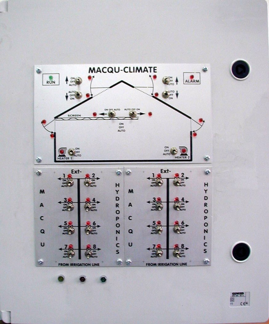
Front view of a typical MACQU Controller Box containing: One typical Main Mimic Switching and Indicator Panel & Two typical Extension Mimic Switching and Indicator Panels |
MACQU ELECTRONICS
HARDWARE SPECIFICATIONS
|
|
Front view of a typical MACQU Controller Box containing: One typical Main Mimic Switching and Indicator Panel & Two typical Extension Mimic Switching and Indicator Panels |
All MACQU Systems (Hydroponics, Climate, Fish, etc.) are equipped with one Controller Box (See Picture 1). The Controller Box is mainly the same for all Macqu Systems. It differs only in the “Main Mimic Switching and Indicator Panel” and the connections in the Main Clemens of Macqu Controller Box.
The Controller Box consists of:
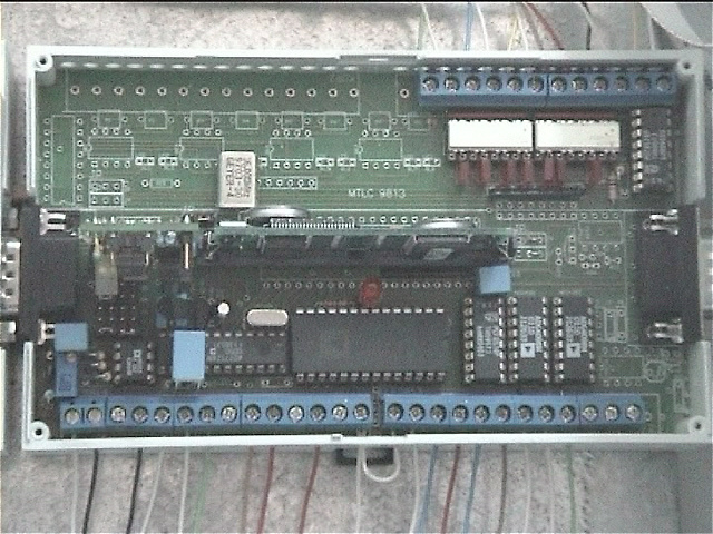
One MACQU-M card which is the main controller of the system. This card has the Analog to Digital (A/D) converter, 8 Digital Inputs (DI), 8 Digital Outputs (DO) and the Communication RS-232 module.
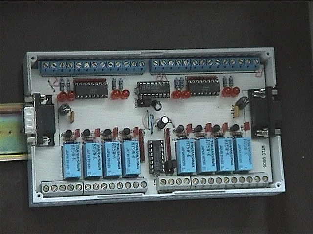
At least one MACQU-Ext card which is a Digital I/O card. There are two types of MACQU-Ext cards, one with 8 Digital Inputs and 8 Digital Outputs (MACQU-Ext-I/O) and one with 16 Digital Outputs (MACQU-Ext-O). There is no limit for the number of MACQU-Ext cards that one Macqu system can support.
A power supply card MACQU-PS, which produces the necessary voltages needed by MACQU-Ext and MACQU-M. MACQU-PS is either supplied by 220 Volt current (110 for USA and JP) or by the 6 Volt Backup Battery in the absence of network power.
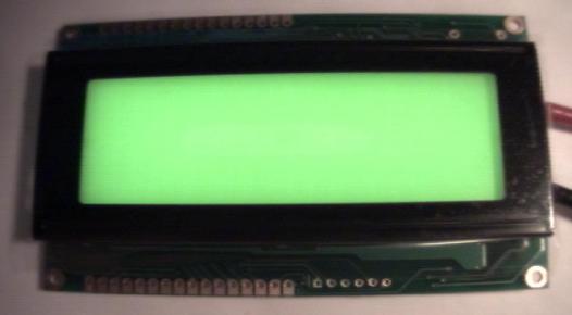
A 4x20 Character Display MACQU-Dis. The information displayed can be changed from Macqu Program and the value of all the variables used in the system can be shown.
One Main Mimic Switching and Indicator Panel with the appropriate mimic diagram depending on the specific application. The panel is equipped with a number of three position switches (on, off, auto) and indicating leds, which allow the user to control the system either manually or automatically. Depending on the application it may have additional alarm or working mode leds.
MACQU-M: Main Controller Card:
|
|
MACQU-Ext: Extension Card I/o
|
|
MACQU-Dis: 4 x 20 LCD Display Panel
|
|